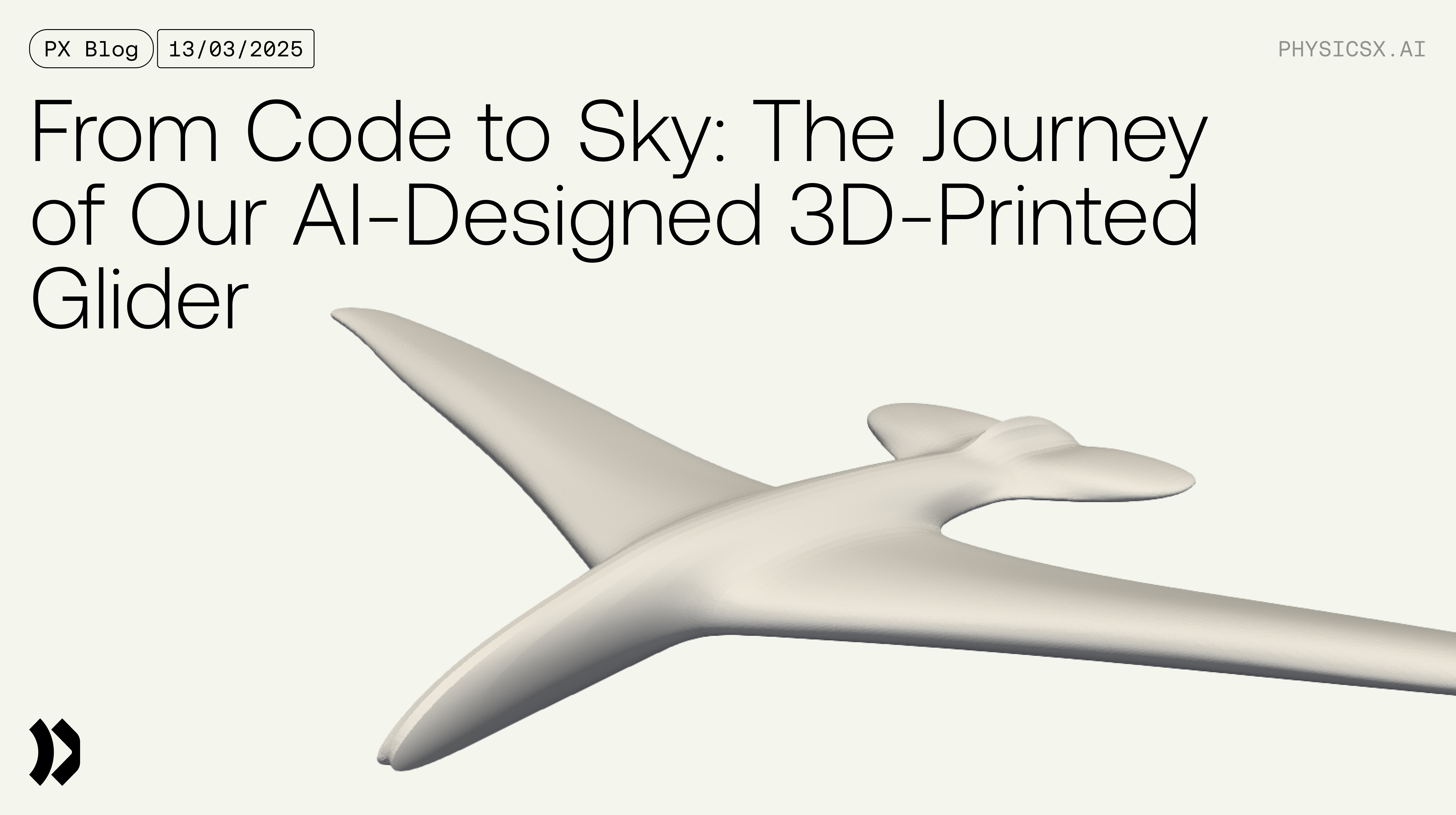
The surge in 3D printing has transformed rapid prototyping, turning it from an industrial tool into a creative one. As both individuals and businesses increasingly use this technology for everything from functional brackets to intricate models, we at PhysicsX have adopted it for a key purpose: bringing the output of our ML models to life in the physical world. Instead of focusing on technical specifications, this article showcases how we leverage 3D printing to bridge the digital and physical realms and assess the real-world impact of our innovations.
In aerospace, before a plane ever takes to the sky, engineers run countless high-fidelity simulations on individual components and the full aircraft to ensure it will perform as expected. PhysicsX is building AI to enhance this process, helping simulation engineers accelerate development and iterate more efficiently on both individual parts and overall aircraft designs.
But how do we ensure that our AI model is comparable in accuracy to traditional simulations and that its predictions reflect real-world physics? While we typically validate AI outputs against simulation data, this time, we've taken a more hands-on approach — producing a physical 3D model to test whether our predictions hold up in practice. Let’s explore the process and the insights we gained along the way.
Finalizing the Design
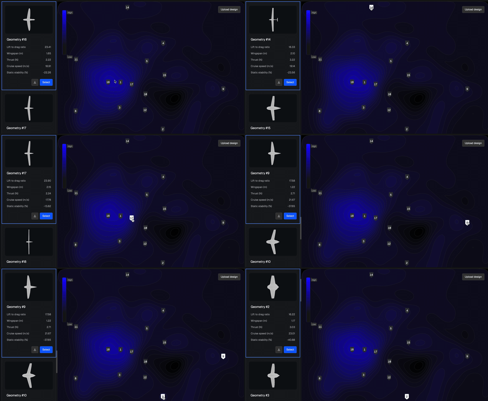
A few months ago, we unveiled our generative AI model, LGM-Aero, to the public through the Ai.rplane application (you can read more about it here). To demonstrate that our model creates truly flight-worthy designs, we decided to bring one of its digital creations into the real world.
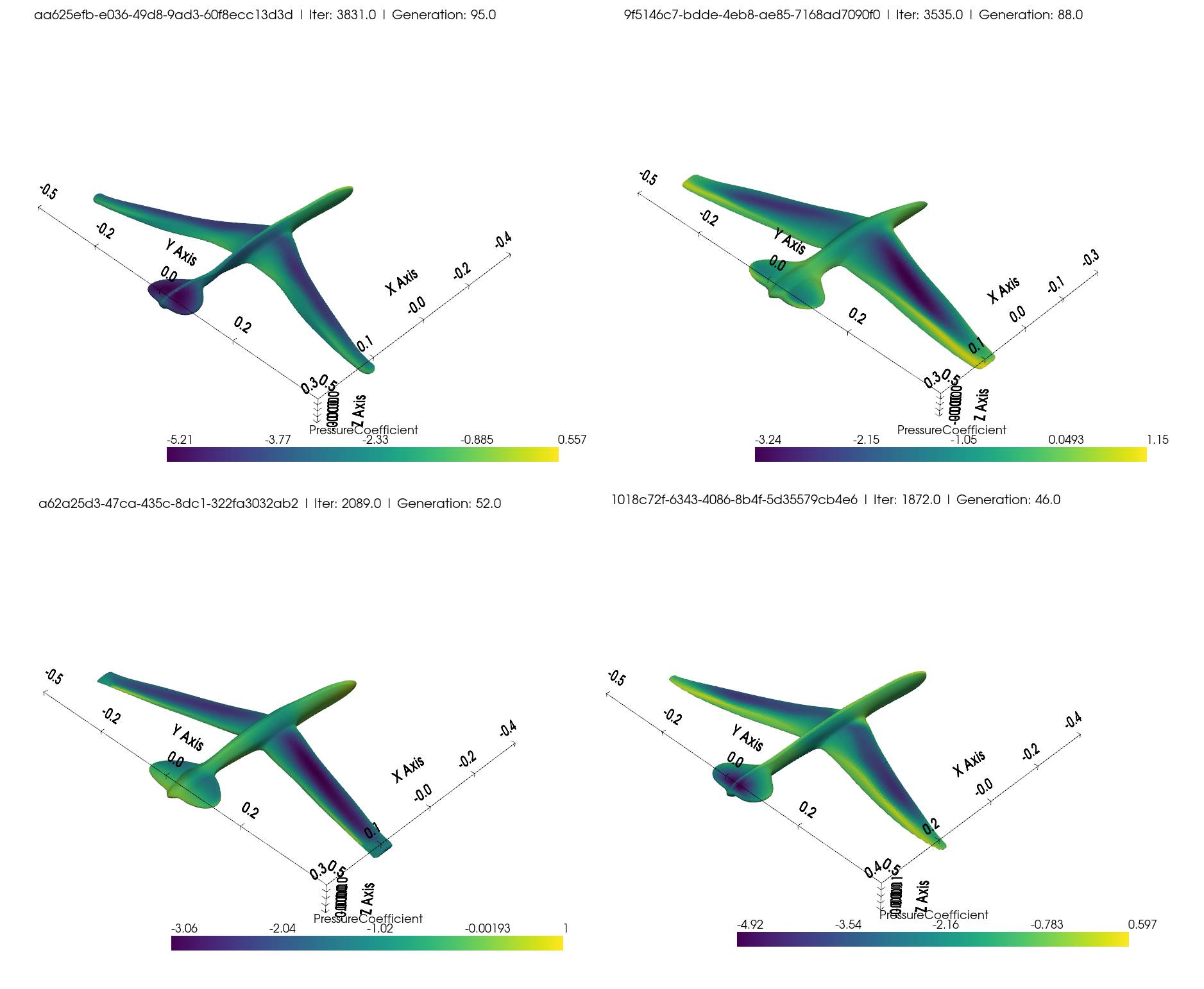
Selecting the ideal geometry was a challenge in itself. We had to consider material constraints, weight limits, size parameters, and target flight speed. We then fed the requirements into an optimization process that explored our generative model’s design space to identify viable candidates. After generating multiple designs and validating them with classical simulations, we chose the best-performing geometry for 3D printing and real-world testing.
Launch Strategy
As we finalized our design through optimizations and simulations, we also faced the challenge of getting our plane airborne. With a 1-meter wingspan and a weight of ~1.2kg, a simple hand launch wouldn’t be enough. After exploring various options, we chose an off-the-shelf plane launcher — offering the power and stability needed to properly test our AI-generated aircraft.
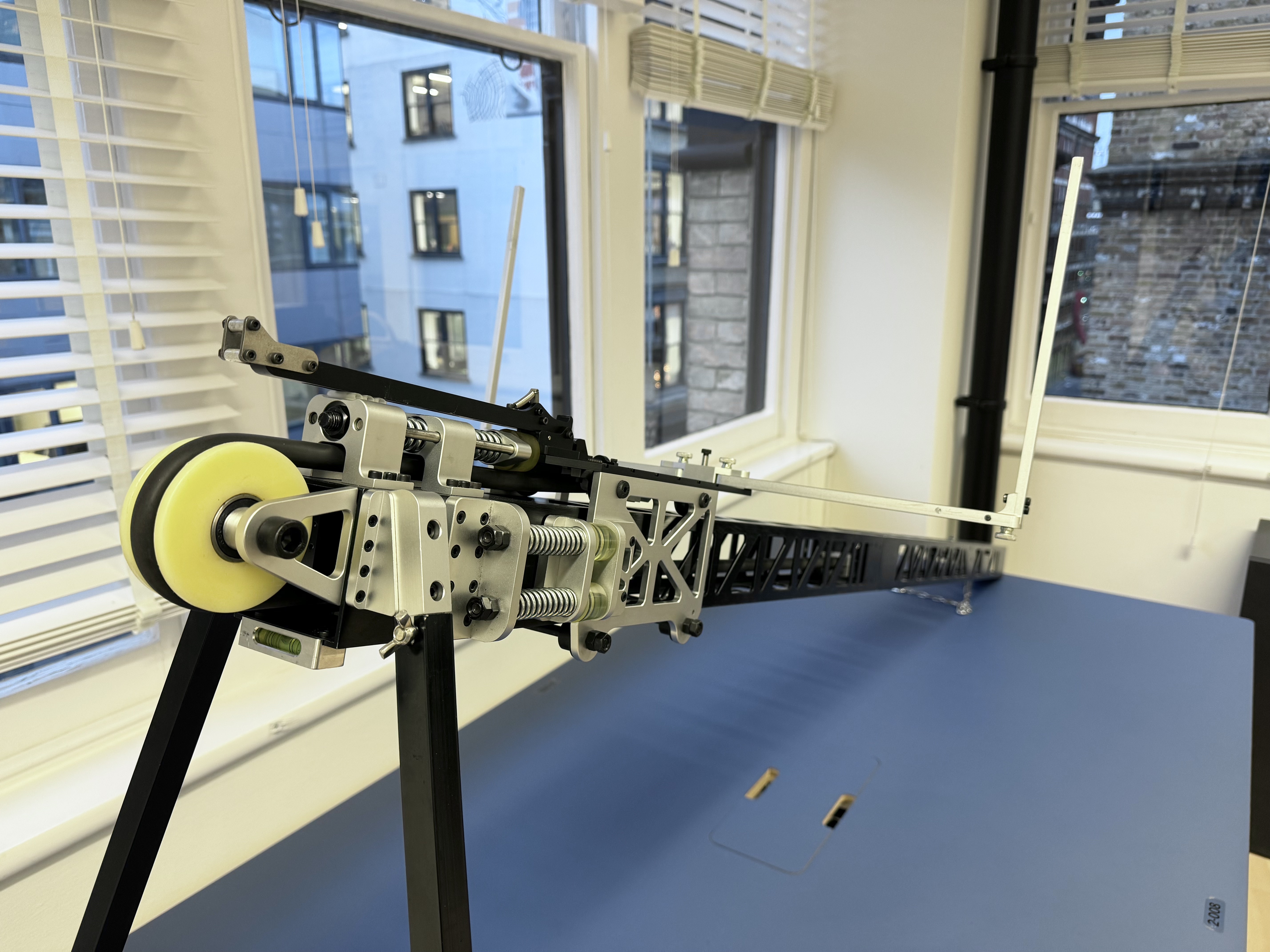
The launcher — essentially a modern ballista — features an aluminum frame and a high-tension rubber band for propulsion. We integrated its specifications into our optimization constraints, designing a 1-meter wingspan aircraft optimized for 10 m/s flight while keeping weight to a minimum.
Experimenting with 3D Printing
After finalizing our design, we faced the challenge of printing it effectively — balancing weight, material selection, and durability. We tested several options:
- Low-weight PLA: A foaming plastic lighter than standard PLA but too brittle — shattered on impact.
- PETG: A PLA/ABS blend with a good strength-to-printability ratio.
- TPU (95A): A flexible, rubber-like material that was extremely difficult to print.
- Construction foam in a PETG shell: A hollow PETG exterior (0% infill) filled with construction foam for lightweight rigidity.
We conducted small-scale test prints to rapidly experiment with materials, designs, and printer settings. These miniature planes provided crucial insights — and the perfect excuse for impromptu office flight tests (with varying survival rates).

Each material offered distinct advantages, ultimately leading us to build our full-scale 1-meter wingspan prototype using TPU. We also considered PETG for its excellent strength-to-weight ratio, particularly at higher infill percentages. Our optimization results for the selected design suggested 22% infill with three perimeter wall lines, striking the ideal balance between structural integrity and weight. With materials tested and design finalized, we faced our next challenge: printing and assembling the complete full-scale model.

Moving from Small Scale to Large Prototype
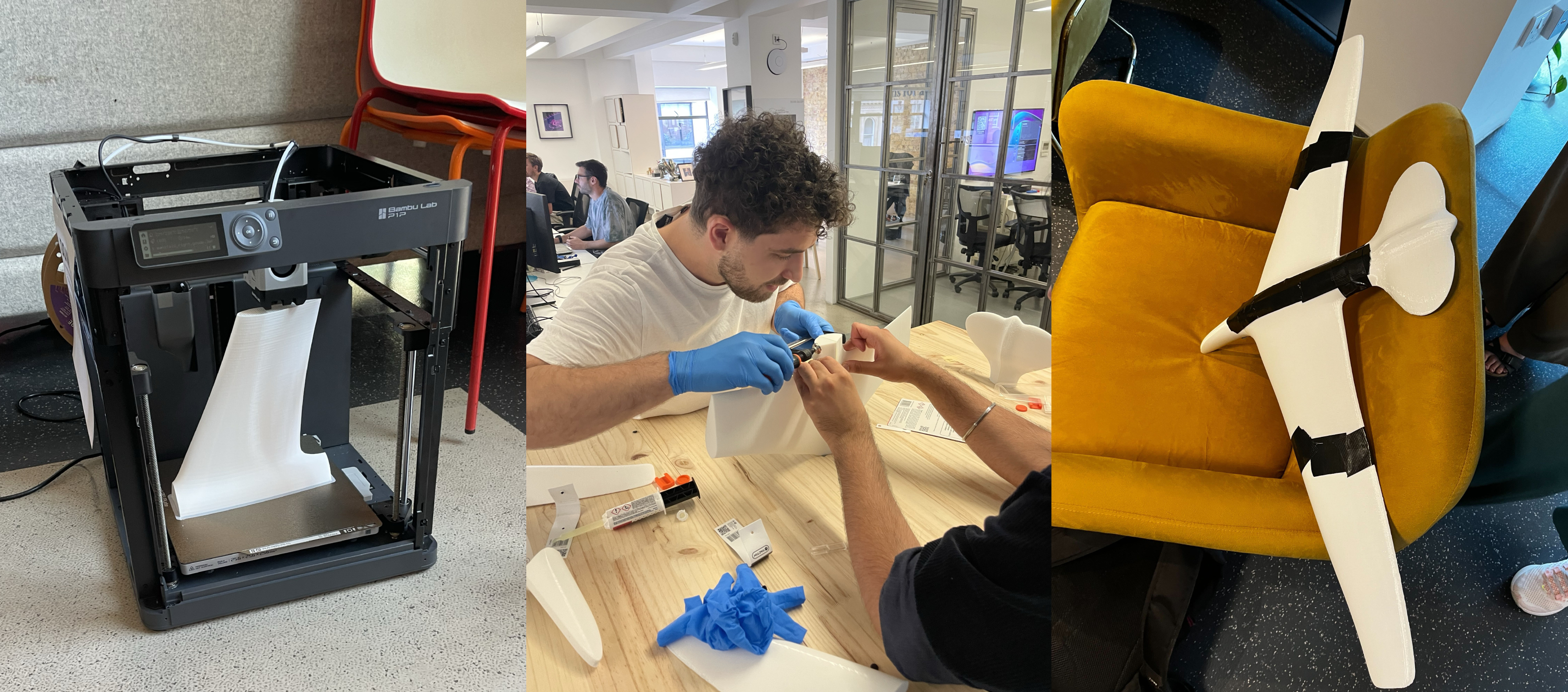
Scaling up to a full-sized model introduced new challenges, especially the risk that the launcher's power could break the plane under initial acceleration forces. We consulted mechanical engineering colleagues for structural reinforcement ideas. Suggestions included carbon rods for wing support, wooden beams through the nose and fuselage, or combining both approaches — and, of course, lots of glue!
The launcher attachment point raised another concern: would the nose withstand the launch force without tearing off? For our first attempt, we opted for a straightforward solution — using only plastic, epoxy, flexible rubber-based shoe glue, and duct tape (the universal engineering fix).
The Question: Did it Fly?
For our first flight test, we chose an aircraft hangar to minimize variables like wind, giving our glider optimal conditions for success. But the question remains — did it actually fly? Well, if one second of airtime counts as a flight... then technically, yes, it flew!
Our glider's initial performance fell short of expectations. After analyzing potential causes, we determined that the launcher's insufficient speed was the main issue — it simply couldn’t generate the speed our optimization calculations required, preventing the aircraft from experiencing its intended flight conditions. By analyzing multiple test flights in slow motion, we identified three critical problems:
- Launcher force loss: The launcher’s force is slightly diminished due to its backward movement during launch. It needs to be better anchored to prevent this energy loss.
- Launcher mounting: The mount holding the glider’s wings is causing an issue. As the plane is launched, the mount hits the tail, creating unwanted rotational momentum.
- Incorrect angle of attack: The plane is pointing too far downward at launch, meaning its angle of attack is off and the aerodynamics aren’t optimal.
Our first adjustment — repositioning the mounting and placing the launcher against a wall — created new issues without resolving the original problems. The launcher now moved forward instead, and the mounting system performed unexpectedly. We then implemented more comprehensive modifications: blocking forward launcher movement, shortening mounting arms, and adding L-brackets with zip ties for angle of attack adjustments. These changes brought some improvements, though inconsistent launch angles still resulted in either nose dives or excessive pitch.
With persistent refinement of the angle of attack, we finally achieved a smooth flight path and landing. While still underpowered compared to our design specifications, this represented significant progress in validating our AI-generated design under real-world conditions.
From our testing, we identified two critical improvements: modifying the launcher to match our AI's predicted launch conditions and increasing launch speed to properly showcase the glider's aerodynamics. To implement these changes, we:
- Redesigned the mounting system for an adjustable angle of attack.
- Stretched the rubber band to boost launcher power.
- Elevated the launch position to extend flight time and allow aerodynamics to take effect.
Once the launcher modifications were complete, we waited for the perfect conditions — remarkably clear and sunny British weather — before attempting our next launch.
After all the fine-tuning, we finally had a proper flight. The launcher was now perfectly tuned for the aircraft, with the correct angle of attack and a bit more power from the stretched rubber band. The plane was up in the air, and it looked great — but we still didn’t see the stability fully kicking in as we’d hoped. Since we couldn’t launch any faster to improve the aerodynamic stability, the next step was to get the plane higher up. More altitude would give us the opportunity to see the physics in action.
Our latest attempt, as seen below, resulted in another really good flight — and we even managed to perfectly hit the piñata! Towards the end of the video, you can clearly see the glider pitching back up, proving that the glider’s stability was finally kicking in. It was a significant moment for us, validating the progress we’d made after all the tweaks. We were thrilled with the results and decided to conclude the tests of our glider with this experiment.
What We Learned
The fusion of AI and 3D printing is absolutely amazing. We successfully validated that geometries and predictions from Ai.rplane are accurate and reliable — and we did it in a fun, hands-on way. While CFD simulations had already confirmed our design's viability, physically building and testing the glider provided invaluable insights into real-world challenges.
3D printing offered tremendous flexibility for iterative optimization, though not without challenges. The process required significant time investment as we discovered that theoretical perfection rarely translates directly to practical application. Our designs lacked vertical tail wings since our AI model computed only longitudinal stability, not lateral stability — an area for future exploration. Material selection was crucial: while PETG worked well for smaller prototypes, it proved too brittle for repeated launches, breaking after just one or two attempts. TPU 95A emerged as the superior choice, absorbing launch impacts while maintaining structural integrity with sufficient infill.
By combining AI, 3D printing, and hands-on problem-solving, this experiment has shown that with the right tools and innovative thinking, we can bridge the gap between digital prediction and physical reality. This is just the beginning, and we’re eager to continue exploring, evolving, and shaping the future of technology — one flight at a time.

